
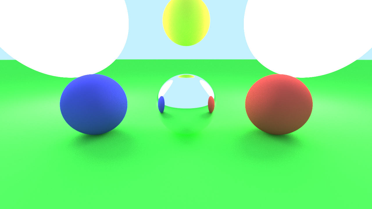
A scene renderer based on the principles of Physically Based Rendering. Written in C++, the renderer used stb_image library for rendering to an image file. The project was done under the mentorship of Mayant Mukul, Stamatics, IIT Kanpur, during early 2021.
The scene renderer renders the objects in a scene using Path tracing. The final output is saved as a .png file.
The project timeline was over a period of 8 weeks with weekly readings, discussion sessions, evaluation tasks, and analysis testing.
Understand the C++ architecture, set up the GitHub repo, build the project using CMake and test out the build application.
// CMakeLists.txt
cmake_minimum_required(VERSION 3.13)
project(pbr)

set(CMAKE_CXX_STANDARD 11)

set(CMAKE_RUNTIME_OUTPUT_DIRECTORY ${CMAKE_BINARY_DIR}/bin)

add_executable(pbr src/main.cpp)
Define the math definition structs for the vector3 data type, rays, and spheres.
// math_definitions.h
struct Vec
{
    float x;
    float y;
    float z;
};

struct Ray
{
    Vec origin;
    Vec dir;
};

struct Sphere
{
    Vec origin;
    float radius;
};
Render a scene using a custom camera. The basis vectors of the camera are calculated based on the look-at value and camera position. Rays from the camera to the screen are made to intersect with the screen object. On a successful intersection, we assign a color value to that pixel.

Basis calculation for the camera:-
// camera.h
void calculate_basis(double aspect_ratio)
{
    Vec look_dir = normalize(look_at - position);
    Vec world_up(0, 1, 0);
    Vec camera_right = cross(look_dir, world_up);
    Vec camera_up = cross(look_dir, camera_right);
    double Lx, Ly;
    Lx = tan(fov);
    Ly = (1 / aspect_ratio) * Lx;
    w = position + look_dir;
    u = (camera_right * Lx / 2.0);
    v = (camera_up * Ly / 2.0) * (-1.0);
}
Intersection b/w rays from camera to screen and scene actors i.e. spheres.
// math_definitions.h
bool intersect(const Ray &ray, Vec &point) const
{
    ...
    if (d < 0)
    {
        return false;
    }
    double l1 = (-b - sqrt(d)) / (2 * a);
    double l2 = (-b + sqrt(d)) / (2 * a);
    if (l1 > M_EPSILON && l1 < l2)
    {
        point = ray.origin + ray.direction * l1;
        return true;
    }
    else if (l2 > M_EPSILON)
    {
        point = ray.origin + ray.direction * l2;
        return true;
    }
    else
    {
        return false;
    }
}
A ray depth of more than 1 will result in a greater number of intersection checks. This allows us to show reflections in objects. Diffuse and Specular samplers can be defined for objects. Ray offset will allow us to capture realistic lighting for rough surfaces.

Discrete sampler used for lighting and color values to be used for the various material types.
// integrators.h
struct DiscreteBRDF
{
    Colorf operator()(const Ray& in, const HitResult& hit, const Ray& out) const
    {
        switch (hit.material.type)
        {
            case EMaterialType::DIFFUSE:
            {
                double diff = clamp(cosv(out.direction, hit.normal));
                return hit.material.color * diff;
            }

            case EMaterialType::SPECULAR:
            {
                return PBR_COLOR_WHITE;
            }

            default:
                return hit.material.color;
        }
    }
};
Pathtracer for the scene which loops based on the ray depth and returns the final color value for a pixel.
// integrators.h
Colorf trace_ray(const Ray& ray, int depth) const
{
    if (depth >= PBR_MAX_RECURSION_DEPTH)
    {
        return PBR_COLOR_SKYBLUE;
    }

    HitResult hit;
    if (intersect_scene(ray, hit))
    {
        auto samples = sampler(ray, hit);

        Colorf result = Colorf { 0.0 };
        for (const auto& sample_ray : samples)
        {
            Colorf tr = Colorf { 1.0 };
            if (sample_ray.direction.len() > PBR_EPSILON)
            {
                tr = trace_ray(sample_ray, depth + 1);
            }

            Colorf coeff = brdf(ray, hit, sample_ray);
            result = result + coeff * tr;
        }

        return result;
    }
    else
    {
        // If there's no intersection, return a light blue color
        return PBR_BACKGROUND_COLOR;
    }
}
Implement the grid sampler for the scene. For any point in the scene, define a 3D grid, and find the current cube. Subdivide the cube into smaller components and derive random rays inside it. Store these rays in an array and return the list.

// integrators.h
struct GridSampler
{
    ...
    std::vector<Ray> operator()(const Ray &in, const HitResult &hit) const
    {
        ...
        // Stores the 8 rays from the center to the vertices on the Cube.
        std::vector<Ray>  result(8);
        for (short i = 0; i < 8; ++i)
        {
            // Add + or - half_side to each component
            int kx = (i == 2 || i == 3 || i == 4 || i == 7) ? -1 : 1;
            int ky = (i >= 4) ? -1 : 1;
            int kz = (i == 1 || i == 2 || i == 6 || i == 7) ? -1 : 1;

            result[i].origin = center;
            result[i].direction.x = kx * half_side;
            result[i].direction.y = ky * half_side;
            result[i].direction.z = kz * half_side;
        }
        ...
        for (size_t i = 1; i < PBR_GRID_SAMPLER_SIZE; ++i)
        {
            for (size_t j = 1; j < PBR_GRID_SAMPLER_SIZE; ++j)
            {
                for (size_t k = 1; k < PBR_GRID_SAMPLER_SIZE; ++k)
                {
                    // Subdivide cube
                    Vec dir = AB * h * i + AD * h * j + AF * h * k + result[0].direction;

                    // Push ray to result
                    Ray ray{};
                    ray.direction = normalize(dir);
                    ray.origin = center;
                    result.push_back(ray);
                }
            }
        }

        return result;
    }
};
Sample points randomly inside a circle and return the result as an image. The points can be sampled in two ways.
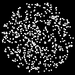

We plot random points inside a square and check whether it lies inside our circle. If a point clears both the parameters, we render it as part of the image.
// sampler.h
std::vector<Point> sample_unit_circle(size_t n)
{
    ...
    while (!hasSample)
    {
        Point p;
        p.x = (((double)rand()) / RAND_MAX) * 2.0 - 1.0;
        p.y = (((double)rand()) / RAND_MAX) * 2.0 - 1.0;
        if (is_inside_circle(p, point_scaling))
        {
            points.push_back(p);
            validSamples++;
        }
        ...
        if (validSamples >= n)
        {
            break;
        }
    }
    ...
    return points;
}
We find a random radius smaller than our circle’s raidus and an angle theta. We can use these polar coordinates (r, t) to get out point (x, y).
// sampler.h
std::vector<Point> sample_unit_circle_center(size_t n)
{
    ...
    while (!hasSample)
    {
        double distance = (((double)rand()) / RAND_MAX);
        double theta = 360.0 * (((double)rand()) / RAND_MAX);
        Point p;
        p.x = distance * point_scaling * cos(PBR_DEG_TO_RAD(theta));
        p.y = distance * point_scaling * sin(PBR_DEG_TO_RAD(theta));
        if (is_inside_circle(p, point_scaling))
        {
            points.push_back(p);
            validSamples++;
        }
        ...
        if (validSamples >= n)
        {
            break;
        }
    }
    ...
    return points;
}
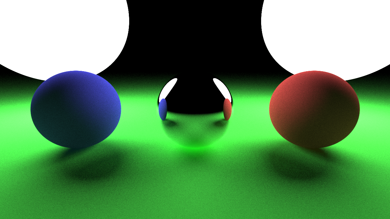
We can expand upon the 2D sampler from week-5 to create a uniform sampler. We find a polar coordinate in the format (r, t, p) by generating them randomly. The polar coordinate can be used to find a random point inside a sphere with the hit-point as center. With this hit-point and random point, we can generate a set of random rays for sampling.

// intergrator.h
struct UniformSampler
{
    ...
    std::vector<Ray> operator()(const Ray &in, const HitResult &hit) const
    {
        std::vector<Ray> result;
        for (int i = 0; i < PBR_NUM_SAMPLES; i++)
        {
            double theta = 2 * PBR_PI * (((double)rand()) / RAND_MAX);
            double phi = 2 * PBR_PI * (((double)rand()) / RAND_MAX);
            Ray r;
            r.origin = hit.point;
            r.direction.x = cos(theta) * sin(phi);
            r.direction.y = sin(theta) * sin(phi);
            r.direction.z = cos(phi);
            result.push_back(r);
        }
        return result;
    }
};
Implemented the stratified sampler in the main function. While iterating over the pixels, we can subdivide the pixels, choose random samples from those pixels, and use the coordinates for the lighting calculation.
// main.cpp
int main()
{
    ...
    double c_x, c_y, d_x, d_y;
    c_x = 0.5 * (i % 2) * 2 - 1;
    c_y = 0.5 * (((i % 4) < 2) ? 1 : -1);
    d_x = s.x / 2.0;
    d_y = s.y / 2.0;
    double x = ((col + c_x + d_x) / PBR_OUTPUT_IMAGE_COLUMNS) * 2 - 1;
    double y = ((row + c_y + d_y) / PBR_OUTPUT_IMAGE_ROWS) * 2 - 1;
    ...
}
The scene can render objects using material BRDFs such as Diffuse BRDF and Phong BRDF. Similarly, we can implement the Oren-Nayer BRDF for lighting the scene actors. The scene system also allows us to change actor properties and debug new scenes.
//brdfs.h
struct OrenNayarBRDF : public BaseBRDF
{
    virtual Colorf eval(const Ray &in, const HitResult &hit, const Ray &out) override
    {
        // in ==>  camera to point
        // out ==> point to light

        // Roughness calculations
        double sigma = 0.75;
        double A = 1.0 - (0.5 * ((sigma * sigma) / ((sigma * sigma) + 0.33)));
        double B = 0.45 * ((sigma * sigma) / ((sigma * sigma) + 0.09));
        ...
        // Simplified Implementation
        Vec N = hit.normal;
        double L = clamp(dot(out.direction, N));
        double V = clamp(dot(in.direction, N));
        double D = sqrt(1 - (L * L)) * sqrt(1 - (V * V)) / pbr_max(L, V);
        Vec out_plane = normalize(out.direction - N * L);
        Vec in_plane = normalize(in.direction - N * V);
        double C = clamp(dot(out_plane, in_plane));
        auto diff = cosv(out.direction, hit.normal) * (A + (B * C * D));

        return hit.material->color * diff * 2; // 2pi for monte carlo, 1/pi for Lambertian BRDF
    }
};


